Rockets: The Return Flight
Throwing away an orbital-class booster after ten minutes of flight was the most expensive compromise in twentieth-century engineering. Modern aerospace redefines rocket stages as reusable aviation assets subject to extreme aerodynamic stress and precision descent algorithms.
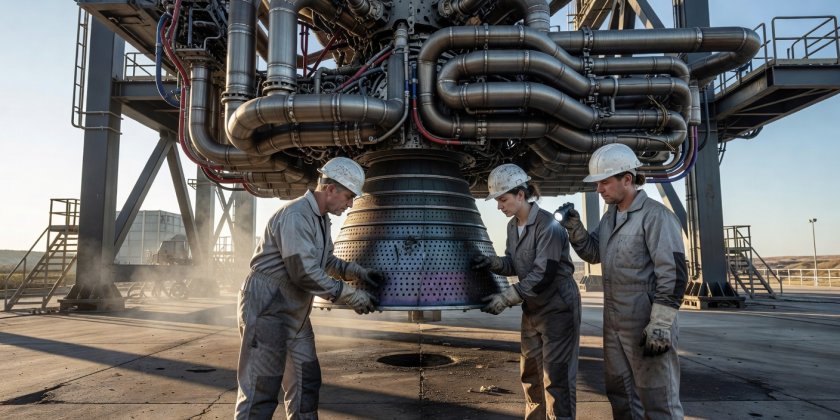
Technicians inspect combustion chamber cooling channels. Photo illustrates real-world metallurgical inspection steps required between test stand cycles.
The Aerodynamic Mechanics of Recovery
Returning an empty booster from hypersonic staging velocities (typically Mach 6 to Mach 9) demands continuous management of dynamic pressure ($q$). At stage separation, the empty booster retains only 4% to 7% of its liftoff mass, turning it into a light, fragile cylinder filled with low-pressure residual gas.
To stabilize this airframe while plummeting tail-first through the upper stratosphere, engineers rely on four titanium or welded-steel grid fins. Unlike conventional control flaps, grid fins operate effectively across both supersonic and subsonic speed regimes, providing roll, pitch, and yaw authority without stalling under violent flow detachment.
Propellant Trade-Offs in Multi-Flight Boosters
| Fuel System | Density & Tankage Mass | Sooting & Coking Profile | Turnaround Impact |
|---|---|---|---|
| RP-1 / Liquid Oxygen | High density; compact aluminum-lithium tanks | Moderate to high soot; requires turbine washing | Proven 15-25 day refurbishment cycles |
| Liquid Methane (CH4) / LOX | Moderate density; larger insulated stainless steel tanks | Virtually zero soot; clean burning cycle | Enables rapid multi-flight reuse with zero wash |
| Liquid Hydrogen (LH2) / LOX | Extremely low density; massive vacuum insulated tanks | Zero soot; clean water exhaust | High cryogenic boil-off; impractical for rapid ground turnaround |
From Landing Legs to Mechanical Tower Catches
Landing legs add parasite mass. Every kilogram allocated to carbon-fiber struts, deployable hydraulic dampeners, and aerodynamic fairings is a kilogram stolen directly from payload capacity to orbit. The development of catch towers—massive robotic chopstick arms integrated into launch mounts—shifts the deceleration equipment from the vehicle to ground infrastructure.
Under this architecture, the descending vehicle throttles its gimbaled center engines to decelerate to zero vertical velocity precisely between the capture rails. The catch pins mounted under the forward grid fins absorb the residual kinetic energy. If executed reliably, it eliminates landing leg maintenance and allows immediate crane transfer onto the launch mount for propellant loading.
Demonstrated Milestones vs. Engineering Hypotheses
Demonstrated: Sea-Level Engine Relight at Mach 2
Re-igniting liquid-fueled engines amid supersonic airflow during entry burns has been performed on hundreds of orbital missions with near-flawless repeatability.
Demonstrated: Upper Atmosphere Aerodynamic Deceleration
Using titanium grid fins to steer unpowered boosters through the sound barrier to within meters of drone ship coordinate targets.
Unproven: 100% Rapid Upper-Stage Reusability
Returning orbital second stages through interplanetary orbital entry velocities without degrading structural thermal protection tiles remains unproven at scale.